
EXPERIMENT NO. 2
AIM
:- Study of forward and reverse characteristics of a pn junction diode.APPARATUS :- Power supply, milliammeter, microammeter, voltmeter, millivoltmeter, rheostat, semiconductor (p-n junction) diode, connecting wires.
FORMULAE:-
i) Forward static resistance, RF = VF / IF
ii) Forward dynamic resistance, rF = (delta)VF / (delta)IF
iii) Reverse static resistance, RR = VR / IR
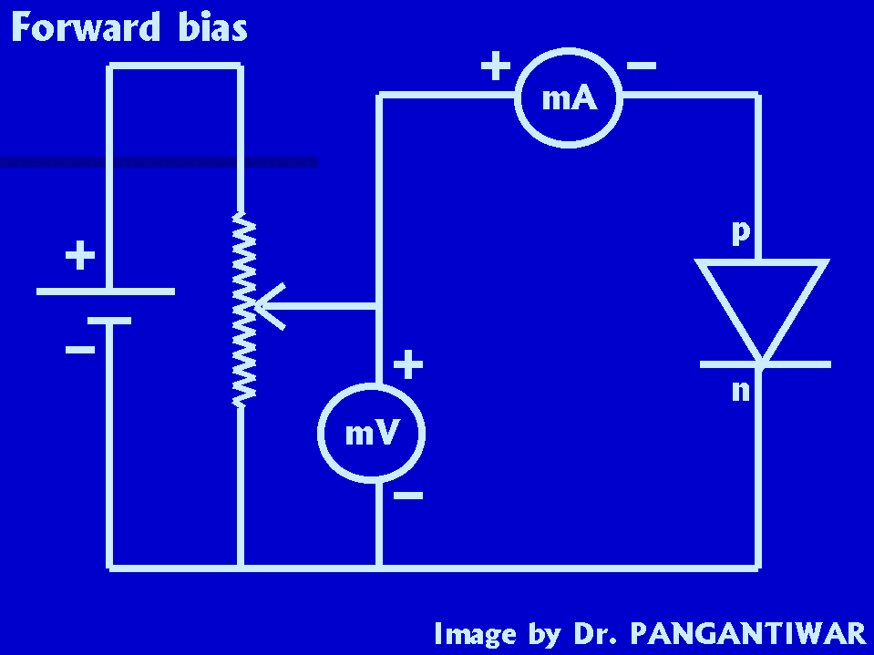
CIRCUIT DIAGRAM:-


PROCEDURE:- Make the connections as shown in circuit diagram for forward bias. Switch on the power supply. The voltage is set at 0 V and the current through the diode shown by milliammeter is recorded. With the help of slider of rheostat, the voltage is increased in steps of 50 mV. For each setting of the voltage, corresponding current shown by the milliammeter is noted. The observatuions are recorded in table.
Then the connections are made as shown in the circuit diagram for reverse bias. The voltage is varied in steps of 1 V from 0 V to 10 V. The corresponding current readings, shown by micro ammeter are noted down. The values are recorded in table.
|
Forward bias |
Reverse bias |
||
|
Voltage (mV) |
Current (mA) |
Voltage (V) |
Current (micro A) |
|
0 |
0 |
||
GRAPH:-
The graph is plotted, by taking forward voltage on the positive x axis and forward current on the positive y axis for forward bias for getting forward characteristics and by taking reverse voltage on the negative x axis and reverse current on the negative y axis for reverse bias for getting reverse characteristics, by selecting suitable scale for forward and reverse bias readings.
From the graph, the cut-in voltage, forward static resistance, forward dynamic resistance and reverse static resistance are calculated.
RESULT:-
i) Forward static resistance, RF =
ii) Forward dynamic resistance, rF =
iii) Reverse static resistance, RR =
iv) Cut - in voltage =
PRECAUTIONS:-