EXPERIMENT NO. 13
AIM
:- To use a prism shaped double refracting crystal to determine the refractive indices of the material corresponding to ordinary and extra-ordinary rays.
APPARATUS :- a quartz or calcite prism, a spectrometer, a sodium vapour lamp.
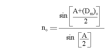
FORMULA :-


where no is refractive index for the ordinary ray.
ne is refractive index for the extra-ordinary ray.
A is the angle of prism.
(Dm)e is the angle of minimum deviation for e-ray.
(Dm)o is the angle of minimum deviation for o-ray.
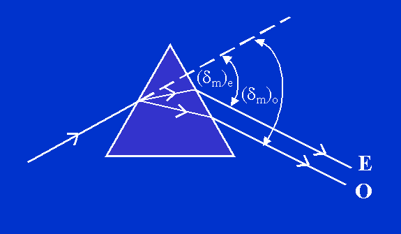
RAY DIAGRAM:-


PROCEDURE:-
- SETTING UP OF THE SPECTROMETER :
1. The spectrometer base is levelled using a spirit level.
2. The prism table is levelled first with the spirit level.
3. The spectrometer is set with the collimator towards the light source. The slit is adjusted to be as narrow as possible. The image of the slit is adjusted to be at the center of the field of view.
4. The eyepiece of the telescope is adjusted such that the crosswires are seen distinctly.
5. The telescope and the collimator are adjusted for parralel rays using Schuster's method.
6. The prism table is levelled optically with the help of prism.
7. The least count of the spectrometer is determined.
- MEASUREMENT OF REFRACTING ANGLE "A" OF THE PRISM :
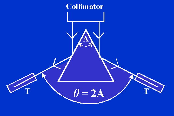
1. The quartz (or calcite) prism is kept on the prism table with its refracting edge at the center and pointing towards the collimator. The light from the collimator is incident upon both the refracting surfaces simultaneously and they give rise to reflected images. See second fig.
2. The telescope is turned first to one side to receive the reflected image. When the image is in the field of view, the telescope is clamped. With the help of the tangential screw, the vertical cross wire of the telescope is slowly moved and it is coincided with the image of the slit. In this position, the reading of the main scale and vernier scale of both windows are read and recorded in Observation Table 1.
3. The telescope is unclamped and rotated to the other side till the reflected image from the second refracting surface of the prism comes into the field of view. When the image of the slit is sighted, the telescope is clamped and with the help of tangential screw, the vertical crosswire is made to coincide with image of the slit. Again the readings of scales from both the windows are recorded in Observation Table 1.
4. The Procedure is repeated thrice. From readings, the angle of the prism is determined. The angle of the prism is equal to half of the difference between the readings in the two positions of the telescope.
- MEASUREMENT OF THE ANGLE OF DEVIATION :
5. The prism table is rotated slowly till the prism base becomes nearly parallel to the collimator beam. The telescope is turned to get the refracted image on the vertical cross wire. Two yellow images of the slit are observed. One yellow image of the slit is coincided with vertical cross wire.
6. Now the prism table is rotated so that the image moves to one side. The telescope is moved with the help of the tangential screw so that it follows the image. Finally a position is reached when the image becomes nearly stationary. A further rotation of the prism table in the same direction makes the spectral line recede. By moving the prism table slowly twicw or thrice, the stationary position of the yellow line is ascertained. The cross wire of the telescope are made to coincide with the yellow line. This is the position of minimum deviation. The position of the telescope is read on both windows. The readings are recorded in Observation Table 2.
7. Now the second yellow image of the slit is coincided with the vertical cross wire. The procedure in step 6 above is repeated to determine the minimum deviation position corresponding to the second image.
8. The prism is removed from the prism table and the telescope is brought to view the image of the slit directly and its position is read and recorded in Observation Table 2. This position corresponds to that of the undeviated image.
9. The angle through which the telescope has been rotated from undeviated position to deviated position gives the angle of minimum deviation.
OBSERVATIONS:-
Observation Table 1 - Angle of the prism "A".
|
Sr.
No. |
Window |
Reflection from first face |
Reflection from second face |
Difference a-b=theta
(Deg.) |
Mean theta
(Deg.) |
A = theta
/2 (Deg.) |
|
MSR (Deg.) |
VSR |
TR
( a ) |
MSR (Deg.) |
VSR |
TR
( b ) |
|
1 |
W1 |
|
|
|
|
|
|
|
|
|
|
W2 |
|
|
|
|
|
|
|
|
2 |
W1 |
|
|
|
|
|
|
|
|
W2 |
|
|
|
|
|
|
|
Observation Table 2 - Angle of minimum deviation (Dm)
|
Ray |
Window |
Reflected Image |
Direct Image |
Diff.
(a) - (b)
= Dm |
Mean Deviation Dm |
|
MSR (Deg.) |
VSD |
T.R. (Deg.) (a) |
MSR (Deg.) |
VSD |
T.R. (Deg.) (b) |
|
o-ray |
W1 |
|
|
|
|
|
|
|
|
|
W2 |
|
|
|
|
|
|
|
|
e-ray |
W1 |
|
|
|
|
|
|
|
|
|
W2 |
|
|
|
|
|
|
|
CALCULATIONS:-


RESULT:-
1. The refractive index for ordinary ray (no) = .
2. The refractive index for extra-ordinary ray (ne) = .
3. The difference [(ne) - (no)] = .
PRECAUTIONS:-
1. The telescope and collimator should be individually set for parallel rays by Schuster's method.
2. Slit should be made as narrow as possible.
3. Both windows should be read.
4. Prism should be properly placed on the prism table for measurement of angle of the prism as well as for the angle of minimum deviation.


