EXPERIMENT NO. 7
AIM
:- Use of a dual trace cathode ray oscilloscope (C.R.O.)APPARATUS :- A dual trace CRO, a signal generator, a resistance box, a capacitance, standard frequency source.
FORMULAE :-

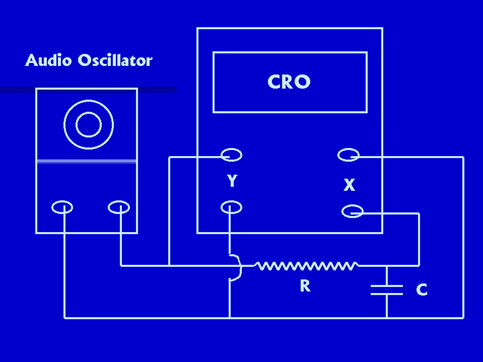
CIRCUIT DIAGRAM:-


PROCEDURE:-
The time base control is set to X-Y-EXT state. In this state the signal given to CH1 input acts as thesweep signal.The vertical mode switch is kept in X_Y position. An ellipse as shown in figure is obtained on CRO screen. The vertical lengths A and B are measured. The frequency of the AC voltages, The values of R and C and the Measurements are noted down. The value of the resistance is changed and the measurements are taken. The procedure is repeated for various settings of R. The observations are recorded in table. Theoretical and experimental values of phase angle are then determined and compared.
The CRO and the signal (AC voltage) generator are connected into circuit as shown in figure. The time base position is kept in X-Y-EXT-HOR position. The frequency of the signal generator connected to Y-input is varied slowly till a stable close looped Lissajous pattern is obtained. The number of loops in the horizontal direction and the number of loops in the vertical direction are counted. The observations are recorded in the table. The frequency is again varied slowly and another stable pattern is obtained and the number are loops are counted. The procedure is repeated for different settings of the frequency and the observations are neatly recorded in table. The frequency of the unknown signal is calculated using the formula. The calculations are counter-checked by comparing them with the actual frequency values from dial setting of oscillator.
OBSERVATIONS:-
|
Sr. |
f |
C |
R |
A |
B |
Phase angle (experimental) |
Phase angle (Theoretical) |
|
1 |
|
Sr. |
Fx |
Lv |
Lh |
Fy |
Dial setting on Oscillator |
|
1 |
RESULT:-
The theoretical and experimental values are found equal.
PRECAUTIONS:-